


Applications
• Telecommunications network exchanges • Storage area networks
• Data centre and enterprise network monitoring
• 10G and 40G circuits
• Mission critical link monitoring
Features & Benefits
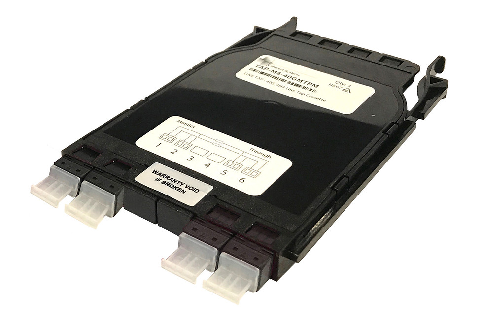
• Modular cassette format offers excellent scaling for multiple circuits in an efficient compact package
• Easy port labelling indicates module wiring to ensure correct connection.
• Easily monitor both 10G and 40G circuits without disrupting live circuits
• Singlemode and Multimode monitoring cassette modules available to suit parallel optics, standard TX-RX pairs and Bidirectional 40G standard.
Test Procedure:
Testing of the optical line tap modules to determine whether they remain within specification or for fault finding may be required from time to time. The procedures required to test the modules is detailed below. Testing the modules is not unlike standard insertion loss testing of fibre links and requires the following equipment. ؠ Suitable light source and power meter with test wavelengths suitable for the module to be tested (850nm for OM4 multimode, 1310/1550nm for singlemode) ؠ Reference test leads suitable for the module to be tested (All MTP modules will require a pair of reference grade Female MTP to LC fanout cables and a Male to Male MTP reference lead, MTP/LC modules will require an additional Male MTP to LC fanout cable, and an LC reference lead) ؠ Through adapters for connecting reference leads ؠ Fibre Optic cleaning equipment
The test procedure for measuring losses through the optical line tap modules are the same as standard procedures for loss testing fibre links using the three cord reference method, however with the addition of a second output.
The steps for testing are as follows:
Step 1. Inspect and if required clean and re-inspect all end faces of your reference leads and the optical line tap module to be tested Step 2. Light source and power meter should be set up and powered on to allow for warm up time for source stabilization
Step 3. Connect the light source to the power meter with the reference leads and through adapters as per the manufacturers recommendations and record the loss value or if the options is available reference the power meter
Step 4. Remove the central reference lead and through adapters
Step 5. Connect the reference leads from the source and meter to the module to be tested, ensuring one tap module input is connected to the source and a matching output is connected to the meter and record the loss for the link (check wiring diagram for input and output details)
Step 6. Disconnect the output reference lead from the cassette module and reconnect to the alternate output associated with the input connected, record the loss for the link
Step 7. Repeat steps 5 & 6 for the remaining inputs (in the case of MTP/LC modules, it is advisable to test the 8 MTP to MTP links, before re-referencing the meter and testing the 8 MTP to LC links as the different output connector types require a different reference lead configuration to test)